CE certificate relay protection testing instrument microcomputer relay protection tester
Six Phase Relay Testing System Protection Relay Testing Equipment Relay Tester
Specification of this Protection Relay Test Kit
| Single phase current output (RMS) | 0 -- 30A / phase, accuracy: 0.2% ± 5mA |
| Six currents in parallel (RMS) | 0 – 180A / 6 same phase parallel output |
| Duty Cycle | 10A continuous |
| Maximum output power per phase | 300VA |
| Max. output power of three phase parallel current | 1000VA |
| Max. output allowable working time of triple parallel current | 10s |
| Frequency range | 0 -- 1000Hz, accuracy 0.01Hz |
| Harmonic number | 2—20 times |
| Phase | 0—360o accuracy: 0.1o |
Test function of the Secondary Current Injection Test Relay Protection Tester
1.Voltage and current test
Select a phase voltage or a phase current as the variable, select automatic or manual test mode change, until the relay acts. When the voltage is greater than 125V and the current is greater than 40a, the line voltage output can be used, such as UAB, UBC and UCA. The current can be output in two-phase parallel or three-phase parallel mode. Note that the current phase should be in the same phase. The high current output time should be as short as possible, and the initial value can be set as 90% of the setting value to shorten the test time. When doing multi-stage over-current protection, it can directly output 1.2 times of current setting value, so that the measured action time is accurate.
2.Frequency test
The default value of the initial frequency is 50 Hz, which can be modified by the user. Select variable frequency, input appropriate frequency step, and click start test. All current and voltage frequencies change.
3.Power direction test
The protection device generally adopts 90 degree wiring mode, and the low voltage setting is 60V. During the test, UA = 60V and phase is 0 degree; UB = 0V and phase is 0 degree; in this way, the line voltage UAB = 60V and phase is 0 degree, and then the voltage is fixed. The amplitude of IC is fixed (generally 5A), and the phase of IC is changed to measure the two action boundary angles. The 90 degree wiring mode is output in the way of "UAB, IC", "UBC, IA" and "UCA, IB".0 degree wiring is output in the way of "UAB, IA", "UBC, IB" and "UCA, IC". Sensitivity angle = (boundary angle 1 + boundary angle 2) /
Features of the Testing Equipment Relay Test
1.6 voltage and current output channel. It can test not only traditional relays and protection devices, but also modern micro-computer protection devices, especially for transformer differential protection and standby automatic switching device. The test is more convenient.
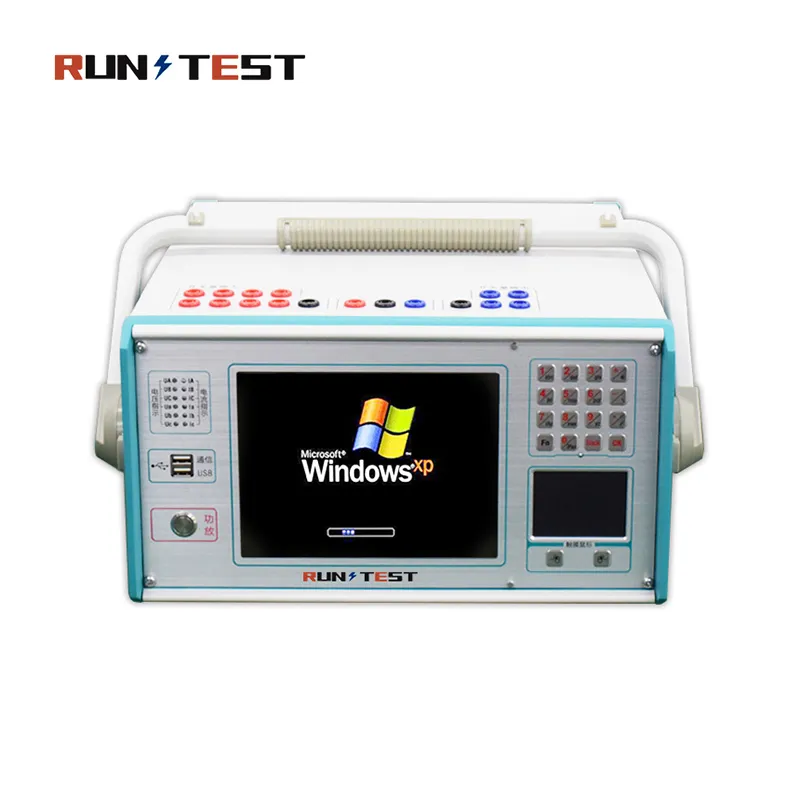
2.Classic Windows operation interface, friendly human machine interaction, easy and fast operation; high performance embedded IPC and 8.4 inch resolution 800 × 600 TFT true color display screen, which can provide rich and intuitive information, including the current working state of the equipment and various help information.
3.Self-recovery function to avoid system crash caused by illegal shutdown or mis-operation.
4.Equipped with ultra-thin industrial keyboard and photoelectric mouse, which can complete all kinds of operations through keyboard or mouse just like PC.
5.The main control board adopts a DSP+FPGA structure, 16-bit DAC output, and can generate a high-density sine wave of 2000 points per cycle for the fundamental wave, which greatly improves the quality of the waveform and the accuracy of the tester.
6.The high fidelity linear power amplifier ensures the accuracy of small current and the stability of large current.
7.USB interface is used to communicate with PC directly without any connecting line, so it is convenient to use.
8.Can be connected to laptop (optional) to run. Laptops and industrial computers use the same set of software, so there is no need to relearn the operation method.
9.It has the function of GPS synchronization test. The device can be built-in GPS synchronous card (optional) and connected with PC through RS232 port to realize synchronous test of two testers in different places.
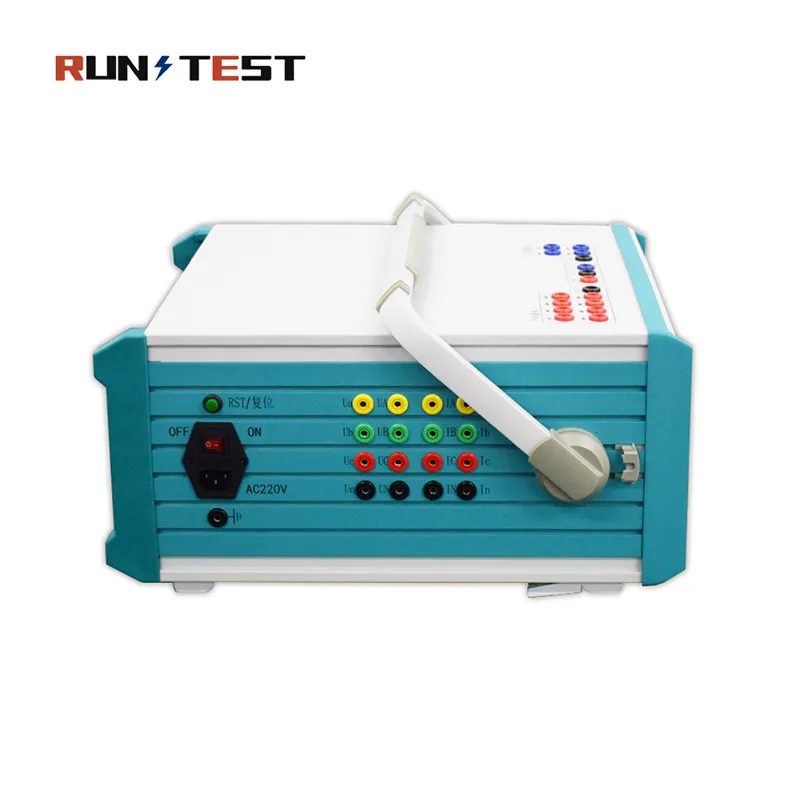
10.Equipped with independent dedicated DC auxiliary voltage source output, the output voltage is 110V (1A), 220V (0.6A). It can be used for relays or protection devices that need DC power supply.
11.It has the function of software self-calibration, which avoids opening the case to calibrate the accuracy by adjusting the potentiometer, thus greatly improving the stability of accuracy.


