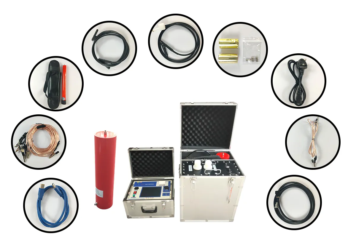
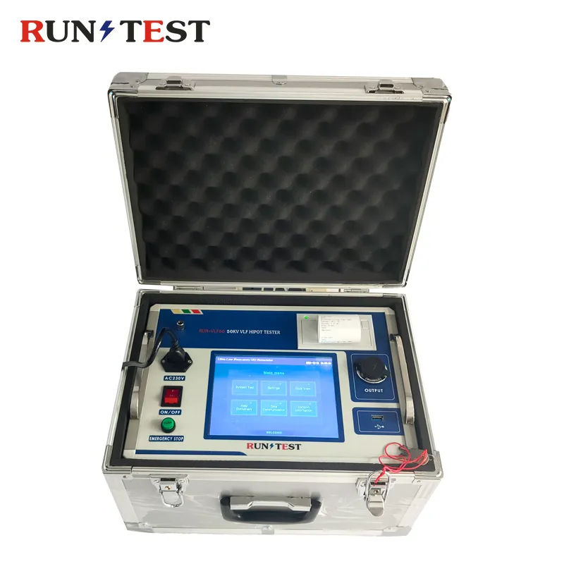
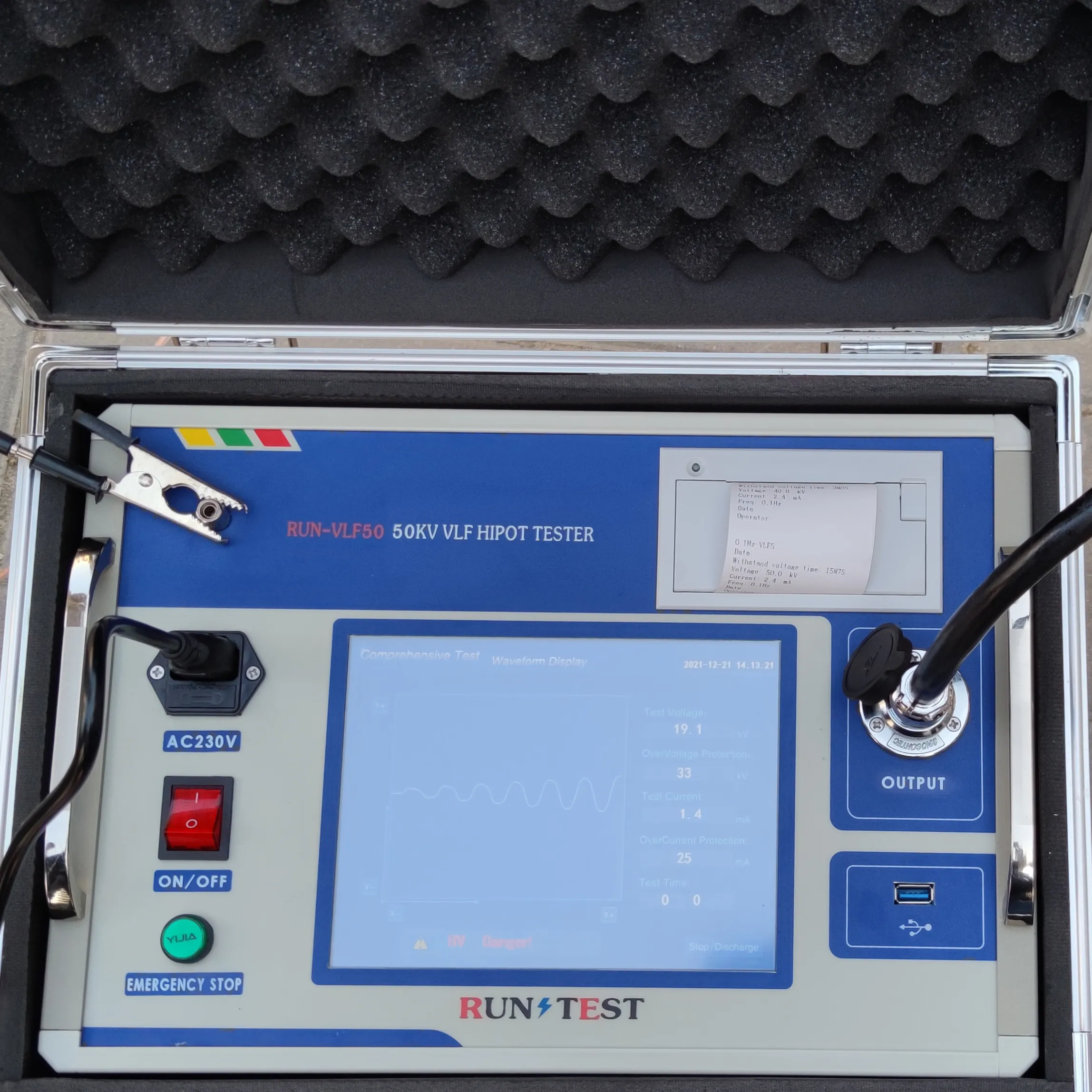
80Kv Very Low Frequency High Voltage Generator AC Hipot Generator
High Voltage Vlf AC Hipot Tester Very Low Frequency Cable Testing Instrument Vlf High Voltage Generator Vlf Hipot Test Kit
Ultra low frequency insulation withstand voltage test is an alternative method for power frequency withstand voltage test.Using 0.1Hz ultra low frequency withstand voltage test replace power-frequency withstand voltage test, not only is equivalent to the same equipment, and greatly reduces the volume and the weight, so the ultra-low frequency withstand voltage device is widely used in large generators, cables, power capacitor test AC voltage withstand test products.
The full electronic design ensures the small size and light weight.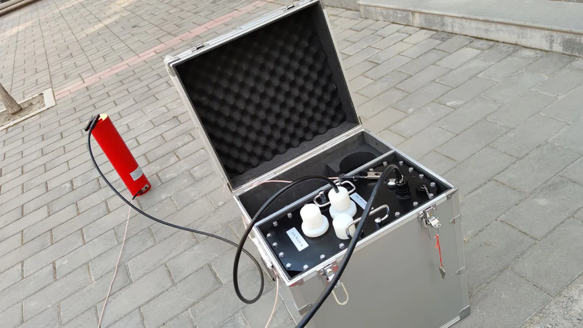
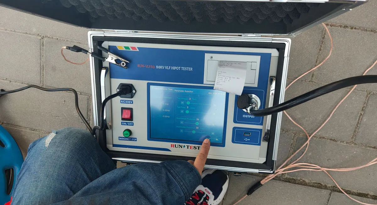
Specification of VLF
|
Output frequency
|
0.1Hz, 0.05Hz, 0.02Hz
|
|
Load capacity
|
0.1Hz maximum 1.1µF
0.05Hz max 2.2µF 0.02Hz maximum 5.5µF |
|
Measurement accuracy
|
3%
|
|
Voltage positive and negative peak error
|
≤3%
|
|
Voltage waveform distortion
|
≤5%
|
|
Conditions of use
|
indoors and outdoors;
|
|
Operating temperature
|
-10℃∽+40℃
|
|
Relative humidity
|
≤85%RH
|
|
Power supply
|
frequency 50Hz, voltage 220V±5%.
|
|
Model
|
Rated Voltages
|
Load capacity
|
Fuse
|
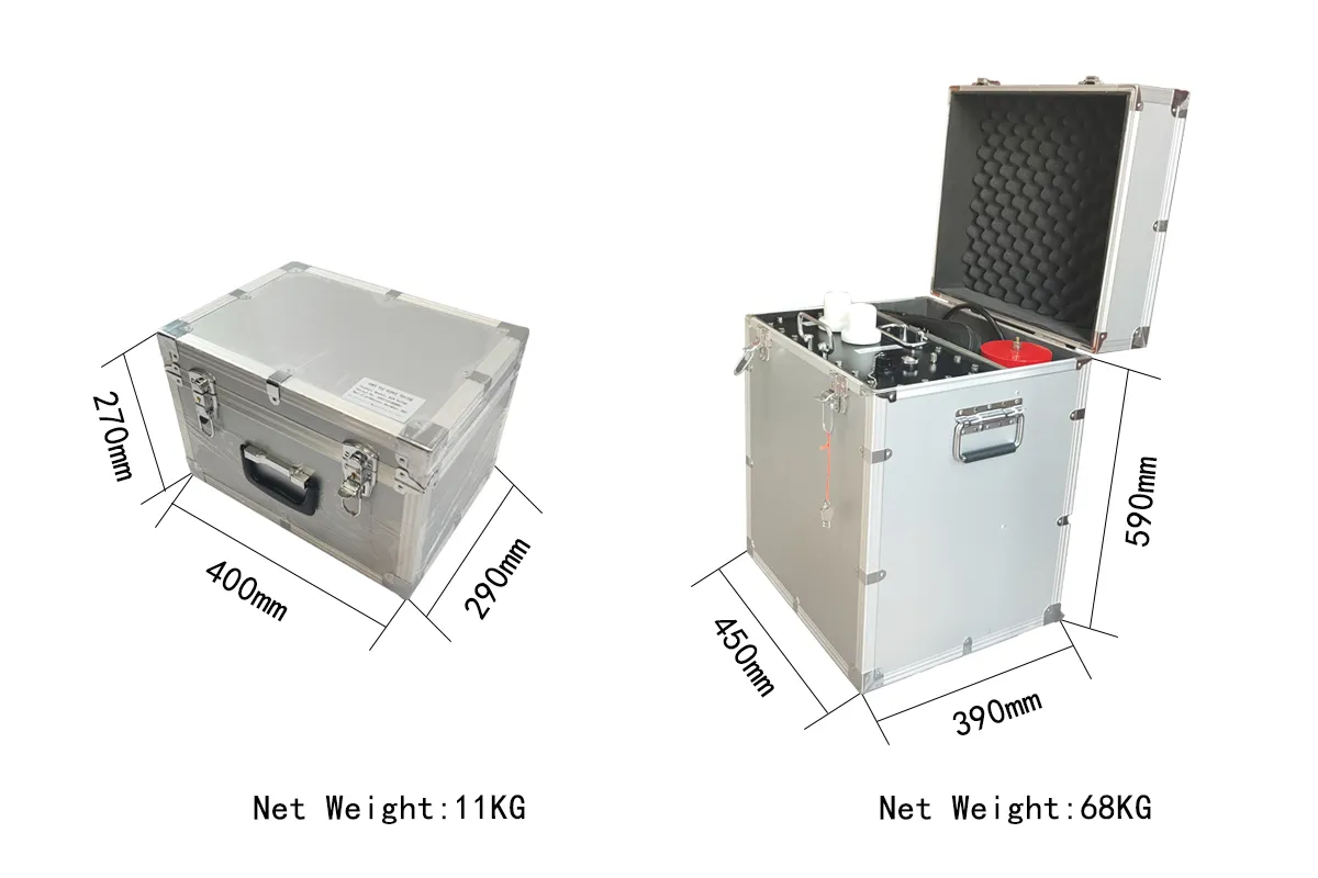
Weight
|
Useful
|
|
30KV
|
30kV
(peak ) |
0.1Hz,≤1.1µF
|
20A
|
Controller:6Kg
Booster:20Kg |
10KV Cables,Generator
|
|
0.05Hz,≤2.2µF
|
|||||
|
0.02Hz,≤5.5µF
|
|
VLF50KV
|
50kV
(peak ) |
0.1Hz,≤1.1µF
|
20A
|
Controller:6Kg
Booster I:40Kg Booster II:60Kg |
15.75KV Cables,Generator
|
|
0.05Hz,≤2.2µF
|
|||||
|
0.02Hz,≤5.5µF
|
|||||
|
VLF60KV
|
60kV
(peak ) |
0.1Hz,≤0.5µF
|
20A
|
Controller:6Kg
Booster I:40Kg Booster II:65Kg |
18KV and below the cable,Generator
|
|
0.05Hz,≤1.1µF
|
|||||
|
0.02Hz,≤2.5µF
|
|||||
|
VLF80KV
|
80kV
(peak ) |
0.1Hz,≤0.5µF
|
30A
|
Controller:6Kg
Booster I:45Kg Booster II:70Kg |
35KV and below the cable,Generator
|
|
0.05Hz,≤1.1µF
|
|||||
|
0.02Hz,≤2.5µF
|
Main features of this ac hipot tester
1. The VLF rated voltage is less than or equal to 50kV adopts a single-connection structure (one booster); the VLF rated voltage is larger than 50kV adopts a series structure (two boosters are connected in series), which greatly reduces the overall weight and enhances the load capacity. The two boosters can be used separately for VLF of low voltage level.
2. Current, voltage, and waveform data are all directly sampled from the high-voltage side, so the data is accurate.
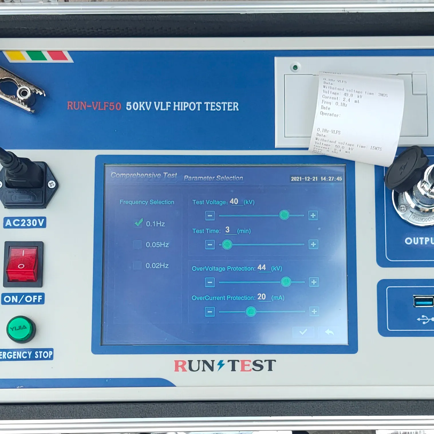
3. With over-voltage protection function, when the output exceeds the set limit voltage value, the instrument will stop, the action time is less than 20ms.
4. With over-current protection function: designed as high and low voltage dual protection, the high voltage side can be accurately shut down according to the set value; when the current on the low voltage side exceeds the rated current, the shutdown protection will be performed, and the action time is less than 20ms.
5. The high-voltage output protection resistor is built in the booster body, so there is no need to connect a protection resistor outside.
6. Due to the high and low voltage closed-loop negative feedback control circuit, the output has no capacity increase effect.
